Charger
Introduction
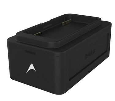
The Vertex One charger is designed to charge the Vertex One PowerPack. The charger is also used to balance batteries and read out error codes of the PowerPack if one would occur.

Specifications
| Specification | Value |
|---|---|
| Input Voltage | 90 - 264 V/AC |
| Input Frequency | 50-60 Hz |
| Maximum Power Consumption (Input) | 460 W |
| Maximum Input Current | 4 A |
| Nominal Output Voltage | 25.2 V/DC |
| Maximum Output Power | 400 W |
| Output Current | 1.0 - 8.2 A |
| Dimensions (LxWxH) | 173 x 100 x 75 mm |
| Operating Temperature | 0 - 30 °C |
Functions & Features
- Charging of Vertex One PowerPack
- Status indicator: LEDs that indicate power-on, charge complete, and errors
- Automatic cell balancing of Vertex One PowerPack
- Universal voltage design – Designed to handle a broad spectrum of input voltages
Product Overview


-
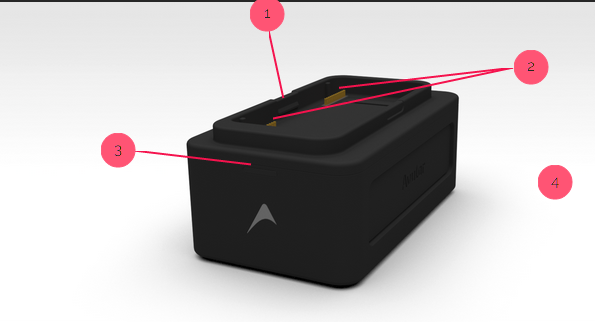
Latching mechanism - Mechanical interface to ensure a proper connection between the PowerPack and the charger
-
Connectors - Electrical interface between the PowerPack and the charger. Used for communication and power
-
Status indicator - Shows battery status using an LED bar; See more details below
-
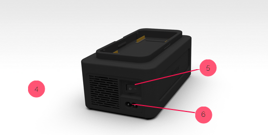
Air venting system - Active cooling ensures the product does not overheat - Attention - Do not cover!
-
Power switch - On/off switch to turn the charger on/off
-
Power entry - Interface for a C7 power cord to power the charger
Instructions for Use
- Plug attached AC power cable (C7 connector) into the charger, then into AC-socket.
- Turn the charger On by switching the on/off switch to On position.
- Mount the PowerPack into the charger. It is mounted when a “Click”-sound from the latching mechanism is heard.
- After initialization both modules start charging automatically. The Charging progress is displayed on the PowerPack modules.
- When charging is complete, the status LEDs on the PowerPack will be off and the status indicator on the charger will be all green.
Note
After the end of charging cycle, the charger automatically stops delivering power to the PowerPack. At this stage, it’s recommended to unplug the PowerPack from the charger and switch off the charger.
Status Indicator
The Status indicator consists of 3 RGB-LEDs.
The middle LED shows the charger status:
| LED color | Description |
|---|---|
| Off | System Off |
| Green | System Powered, OK |
| Red | System Powered, Error |
The charger error is triggered when the internal temperature of the charger exceeds 75 oC. This error will be resolved by letting it cool down.
The left and right LED shows the status of the corresponding PowerPack module.
| LED color | Description |
|---|---|
| Off | Stand-by |
| Green | Charging completed |
| Red (in a blinking pattern) | PowerPack reports an error, see below |
The PowerPack error blinking patterns are stated below. Please consult the PowerPack user manual for the required action(s).
| Error | Blinking Pattern | Remark |
|---|---|---|
| Communication | 1 x pulse + 2 sec silence | The charger cannot communicate with the battery module |
| Cell Under Voltage | 2 x pulses + 2 sec silence | The module is not safe to charge due to deeply discharged cells |
| Cell Over Voltage or Over Charge | 3 x pulses + 2 sec silence | The module is not safe to charge further due to over charged cells |
| Over/under temperature | 4 x pulses + 2 sec silence | The temperature is either too high or too low |
| Over current | 5 x pulses + 2 sec silence | Charging current is too high |
| BMS | 6 x pulses + 2 sec silence | Hard fault triggered in low-level BMS. |
| Miscellaneous | 7 x pulses + 2 sec silence | Other safety error reported by the BMS, that are not related to charging. |
Communication error
Read section Cell Overdischarge
Over/under temperature error
Read section Cooling Down Before/After Charging