Vertex Bridge - SW Integration
Introduction
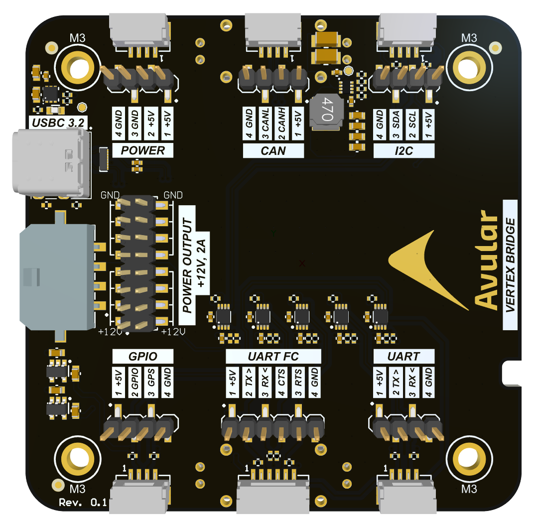
Vertex Bridge offers multiple connectivity options. In this section we explain how to use these to communicate with a connected add-on (e.g. additional sensor).
Connectivity Overview (External)

Connectivity Overview (Internal)

GPIO Connector
GPS Pin
The GNSS module in the Vertex One outputs a synchronised timepulse on the GPS pin. This timepulse is only active when the GNSS has an active fix.
GPIO Pin
The GPIO pin on the Bridge is Jetson GPIO07. See below a Python example code can be used to drive the pin:
import RPi.GPIO as GPIO
import time

# Pin Definitions
output_pin = 12  # BCM pin 18, BOARD pin 12

def main():
    # Pin Setup:
    GPIO.setmode(GPIO.BCM)  # BCM pin-numbering scheme from Raspberry Pi
    # set pin as an output pin with optional initial state of HIGH
    GPIO.setup(output_pin, GPIO.OUT, initial=GPIO.HIGH)

    print("Starting demo now! Press CTRL+C to exit")
    curr_value = GPIO.HIGH
    try:
        while True:
            time.sleep(1)
            # Toggle the output every second
            print("Outputting {} to pin {}".format(curr_value, output_pin))
            GPIO.output(output_pin, curr_value)
            curr_value ^= GPIO.HIGH
    finally:
        GPIO.cleanup()

if __name__ == '__main__':
    main()
UART FC Connector
To send messages to this UART use /dev/ttyTHS0
UART Connector
This UART port is by default the Debug port of the Onboard Compute Unit. This will show the debug output and eventually opens a shell for the user. See this video on how to use it:
How to use Jetson Debug port (External Link)
To send messages to this UART use /dev/ttyTCU0
I2C Connector
The I2C port is connected to bus 8. Some examples of how to use the I2C port are:
To test if your I2C device is properly connected execute i2cdetect -y 8. If it shows the address of your device then the connection is working.
CAN Connector
To use the CAN bus the python-can is an easy to use library. More info here: